Camera calibration is performed to determine image coordinates from the real world coordinates. There are two methods that can be used for camera calibration: (A) folded checkerboard and (B) camera calibration toolbox.
A. Using a Folded Checkerboard
An image of the folded checkerboard is shown in Figure 1 with the convention of the x, y, and z axes.
 Figure 1. Folded checkerboard with axes convention.
25 Points are chosen from the folded checkerboard as shown in Figure 2. The selected points are some corners of the checkers from the folded checkerboard.
 Figure 1. Selected 25 points in the folded checkerboard.
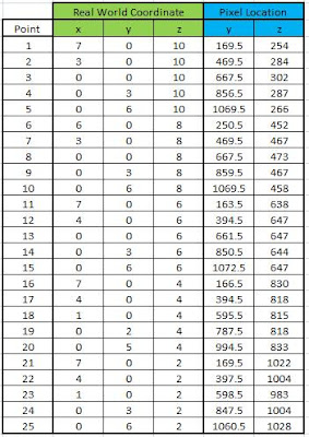
The real world and image coordinates of the chose points are given in Table I. The image coordinates are obtained via the ginput function of Matlab 7.
Table I. Real world and image coordinates of the 25 Points.

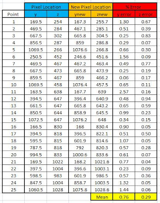
The camera parameters a are obtained from the real world and image coordinates using Equation 33 of Ref. 1. The predicted image coordinates using the camera parameters a are obtained using Equations 29 and 30 of Ref. 1. The predicted image coordinates are shown in Figure 2.
A comparison of the manually obtained and predicted image coordinates is given in Table II. It is observed that the mean errors for the y and z are 0.76 and 0.29, respectively. The small error indicates that camera calibration technique performs properly.
Another method for camera calibration is through a toolbox developed for Matlab. The toolbox can be downloaded from Ref. 2. 20 images of a checkerboard with various translations and rotations are needed for this method. The 20 images are shown in Figure 4.
Using the toolbox, the Matlab GUI will ask to point the edges of the checkerboard. The image with the chosen edges of the checkerboard is shown in Figure 5.
 Figure 5. Selected edges of the checkerboard.
After selecting the edges of checkerboard, the toolbox will ask the user to confirm whether the corners of the checkerboard are all detected. The predicted corners of the checkerboard are shown in Figure 6 for some of the translations and rotations.
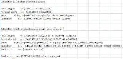
The intrinsic parameters such as the focal length, skew, etc. are outputs of the toolbox. The intrinsic parameters are given in Table III.
Table III. Intrinsic parameters.

The extrinsic parameters such as the translations and rotations of the checkerboard with respect to a camera location (camera-centered) are shown in Figure 7.
The extrinsic parameters such as the camera locations with respect of the checkerboard position (checkerboard-centered) are shown in Figure 8.
I give myself a grade of 10 for this activity.
References:
[1] M. Soriano, A Geometric Model for 3D Imaging, 2009.
[2] http://www.vision.caltech.edu/bouguetj/calib_doc.


No comments:
Post a Comment